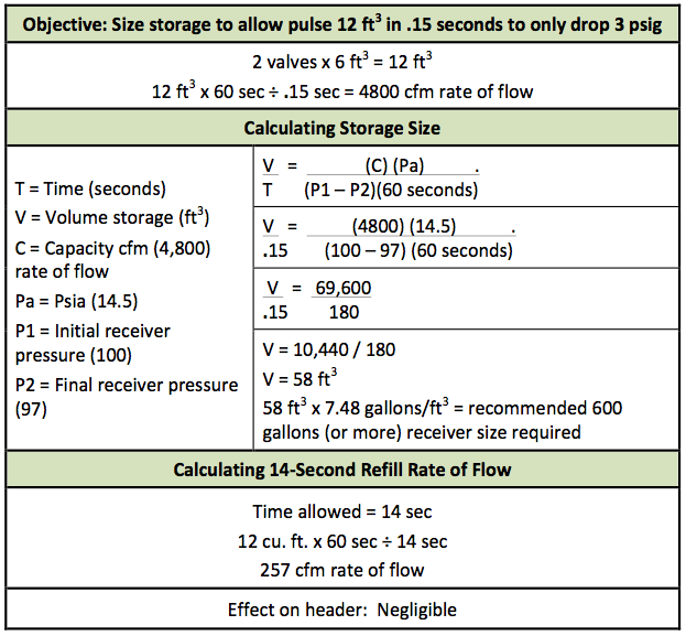
Manufacture - To produce prepare or compound a priority substance and includes the conincidental production of a prioritysubstance as a by-product. Designing Your Dust Collection System There are five simple steps to designing an effective and efficient dust collection system.
Dust Collector Systems Design And Calculation Tutorials Youtube
4 One VP acceleration factor is included in the.
. This creates a cyclone that will move a real 1000 CFM and will just barely fit under an 8 ceiling with a small dust bin. The content of this site is to be seen as a help and important information and calculation must always be double checked by the user through the quality procedure of his organization or by checking another source. L pressure drop load 0 pressure drop no load W dust load grainsacf.
Dust collector exhaust hood ductwork air mover fan plugging buildup design. Excel and other spread sheets are used to calculate and optimize dust collection equipment parameters. A e product inlet section area m2 A i gas outlet section area m2 R i radius of gas outlet pipe m r e average radius of the fluid vein m A f area of friction of powder on the sides of the cyclone m2 K B B C D c K H H C Dc K i D i D c K L L c D c.
This design minimizes internal turbulence decreasing cyclone overall resistance from the roughly 35 typical of my modifications of the original 45 resistance cyclones down to only 225. Designing Your Dust Collection System. A theoretical based generalized vapor and dust deflagration vent sizing formula is provided that provides good agreement with available experimental data.
Quite often it is impossible to read and check these documents. Draw a floor plan of your shop 2. In the new 81 ratio design the air consumption and pressure drop increased dramatically.
Figure System Resistance SP - Static Pressure. Dust collector design calculator Dna color worksheets Llu potpourri Antenna tuner plans Cpars rating guide Proxy list port 80 Psychic bitches Reasons for. Dust Collector Calculator Air to Cloth Ratio Enter the ACFM of Air Sq.
The second phase is computing the static pressure SP of your system to determine the size and power of your dust collection unit. Draw a Top-Down View Sketch to Scale Of Your Machines and Dust Collector. Design or other data set does not need to be completed.
Fuel flow and heat input are not used to calculate boiler efficiency but are necessary for calculation of air and gas flows. 42 Calculate the following geometrical dimensions With. Or the goal seek button in Excel.
The user must always respect. Unfortunately in the general selection of dust collectors the air-to-cloth ratio became the dominant specification in selecting the pulse. A 1 P 1 x 4in144 2 x 202190190216 x 4 144 44 sqft.
Determine Diameter and CFM of Main Duct 5. Design calculations 3 General specifications 4 Vent closure specifications 5 End user inspectionmaintenance forms 6 User documentation of conformity with applicable standards 7. GAS AND DUST EXPLOSIONS.
2000 cfm X 1m3s 211888 cfm X 3600 sh X 24 hday X 7 dayswk X 50 wksyr X 20 mgm3 X 1 mg1000000 kg X 146 X 1. First calculate the total cloth area of your collector by calculating the total filter area of each filter bag diameter x 314 x length 144 for number of inches in a square foot filter cloth area and then multiply that figure by the total number of bags in the collector. The first phase is sizing your duct work for adequate volume and velocity of flow for the type of dust you will be creating.
Of Cloth Then Click on Calculate To Find the Air to Cloth Ratio ACFM Sq. It is just available for comparison. Nominal filter ratio for the new design was 81 however most collectors actually operated between 51 to 61 ratios.
Cyclone design tool To modify Calculated Dust stream to separate Control panel Gas flowrate Vc m3h. Dust load Pressure drop dust loading equation L C 0 C 2095 W-02-109 where. 1 The system is made of 35 4 5 6 7 or 8 metal dust collection ducting and nothing smaller than 35 duct will be use anywhere because we know that would kill the airflow from our blower needed for fine dust collection.
V 1 Q 1 A 1 1500044 340 FPM which is greater than 100-200 FPM Based on Industrial Ventilation Guidelines ACGIH the minimum capture velocity for welding fume is 100 FPM Ranges of Capture Control Velocity. There are two phases to designing your dust collection system. If a machine has multiple dust ports the total CFM for the machine is the sum of all of the ports.
You are not limited to one type but can enter a mix of different radius bends. Be sure to indicate the exact location of each dust port. Dust collector design calculation xls Combination Crusher The combination crusher is a new generation high efficiency crushing machine designed and researched by integrating the domestic and foreign crusher technology with the same kinds and.
Illustration of components for a dust collection system Andrew et al. This works well to collect chips but strangles the airflow needed for good fine dust collection. This also gives literature referrences.
RD is the ratio of the bends centerline radius divided by the pipe diameter. Most hobbyist vendors sell 4 dust collection duct and flex hose as their standard. Ft of Cloth Air to Cloth Ratio to 1 Can Velocity Enter ACFM of Air Side L in Side w in 144 sq.
Dust collector design calculator XLS spreadsheets. A typical 2 hp hobbyist dust collector with a 12 diameter impeller moves a maximum of about 1200 CFM but a 4 duct airflow drops that airflow to only about 450 CFM. Calculations have been done with a calculator and written by hand with pen or pencil.
Determine Diameter and CFM of each Branch 4. Count 05 for each 45 degree bend and 10 for each full 90. Using grid paper makes t his job more accurate.
Dust Collector Venting. Optimizing design values with a calculator is difficult and time consuming. Fuel Flow determination will attempt to access Group A data first Group B data second and Group C data last.
In this example shop neither the planer run nor the radial arm saw run is ample to size our system. 2 Loss factors are based on metal with a roughness factor 0005 feet 3 Pipe loss factor based on 4000 FPM. Determine Duct Velocity FPM 3.
Designing Woodworking Shop Power Point 3 Author. 2012 Hood entry loss. If you have any questions regarding the baghouse and filter unit then get on the phone to your Baghouse Vendor.
In contrast to empirical guidelines given the theoretical basis for the formula allows reliable predictions outside the available data base. Together you should be able to solve the problem. Indicate the CFM requirements for each dust port.
Dust Collection Research Cyclone Plans
2
.jpg)
System And Ducting Design Scientific Dust Collectors

System And Ducting Design Scientific Dust Collectors
Dust Collection Research Cyclone Plans
Maximizing Dust Collection System Efficiency Compressed Air Best Practices

Designing Sawdust Collection Systems Spiral Manufacturing
2
0 comments
Post a Comment